Table of contents
- What is the EEPROM?
- What is the Flash?
- Video related to EEPROM
- EEPROM vs. Flash
- EEPROM Features
- Working principle of EEPROM
- Types of EEPROM memory
- Pros and cons of EEPROM
- EEPROM Failure Mode
- How does EEPROM work?
- How eeprom works in microcontroller?
- EEPROM FAQ
What is EEPROM?
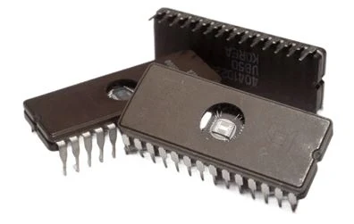
Electrically Erasable Programmable Read-Only Memory, or EEPROM for short, is a form of non-volatile memory used in computers, meaning that the data recorded is retained even if power is removed. It is typically built into microcontrollers like smart cards. By using specific programming signals, it is possible to program and delete EEPROMs inside of a circuit. The lifetime of the EEPROM is a crucial design factor for EEPROMs that are often reprogrammed because we can write and program the IC multiple times in EEPROMs.
The term "flash" is frequently used to represent non-volatile memory having big erase blocks and a short lifetime. Flash is a form of EEPROM built for high speed and high density. However, non-volatile memory with small erase blocks and extended life is frequently referred to as "EEPROM" in this context.
What is Flash?
Flash, which is also known as flash memory, combines the advantages of ROM and RAM with those of NVRAM in that it can read data quickly and is also electronically erasable and programmable (EEPROM).
Video related to EEPROM
EEPROM vs. Flash
The greatest distinction is that while EEPROM offers read and write operations by byte, FLASH reads and writes by block or sector. Additionally, EEPROM capacity is often extremely modest compared to FLASH storage, which can be very big. Once more, these are many application scenarios: Small-capacity data that is dispersed, such as flag bits, a collection of data, etc., is stored in EERPOM.
EEPROM Features
- To read from, write to, or erase data from the EEPROM, two separate voltages are needed.
- The retention time of the chip is constrained.
- It is pricey when compared to other memory alternatives.
- Making adjustments to the serial cell takes time.
- To modify the chip's data, no further hardware is needed.
- Byte by byte data deletion is possible.
- Hardware data protection with write protect pins.
- 16-byte page (4K, 8K, and 16K) and 8-byte page (1K, 2K) write modes.
- Writing partial ages is permitted.
- Automatic writing cycle.
Working principle of EEPROM
The same idea underlies UV-EPROM and EEPROM. The features of the cell will be altered by the trapped electrons in the floating gate, which will cause the cell to store a logic "0" or "1" rather than a logic "0". The memory type that uses the fewest standards for cell design is EEPROM. The majority of cells have two transistors. In this instance, the floating gate on the memory transistor will catch the electrons.
In addition, an access transistor is present for use. The cell is deleted in an EEPROM when the electrons are trapped in the floating cell, as opposed to an EPROM, which erases the cell when the electrons are released from the floating gate. Serial access and parallel access EEPROMs are two distinct groups. Ninety percent of all EEPROMs on the market have serial access, whereas just ten percent have parallel access.
Types of EEPROM memory
| Serial EEPROM Memory | Parallel EEPROM Memory | |
| Definition | Because there are fewer pins on this type of chip, also called an E2PROM, operations must be serialized, making it more difficult to operate. This kind is slower than parallel units because the data is sent in a serial fashion. There are a number of prevalent interface types: 1-Wire UNI/O over SPI Microwire I2C. | Typically, these devices have an 8-bit wide bus. The device typically has pins to block selection and writing operations. There are also certain microcontrollers that can integrate parallel EEPROM for software storage. When compared to serial devices, the chip operates more quickly and simply. This type's larger size as a result of the greater quantity of pins is a drawback. |
| Features |
- Ability to read sequentially - Function to prevent writing because of incorrect instruction recognition - 106 endurance - Capacity for memory: S-93C46B 1 K-bit - Data for the first shipment: FFFFh |
- MIL-STD-883 testing - Internal Error Correction Circuit - Optional software data protection mechanism - Extra bits for device identification - Battery-voltage (2.7V), low-voltage (3V) and 5V devices - Industrial-strength gadget PDIP, PLCC, SOIC, and TSOP are all RoHS compliant - Military-grade ceramic hermetic packaging dual marked with Standard Microcircuit Drawings (SMD) part numbers |
| Applications | EEPROMs are employed in a variety of industries, including telecom, consumer, automotive, and industrial. The reprogrammable calibration data for test equipment and data storage from a learn function similar to a remote control transmitter are some of the other applications. | |
| Serial vs. Parallel | Parallel EEPROM chips can be used in flash and EPROM devices. Compared to the serial EEPROM approach, it features a faster and more reliable data transfer mechanism. Due to the higher pin count, it is larger, denser, and more expensive. These reasons make flash or serial EEPROMs more popular than parallel EEPROMs. | |
Pros and cons of EEPROM
Pros of EEPROM:
- EEPROM is simple to reprogram, and you may do so without taking it out of the computer or using any special tools.
- In contrast to EPROM, which employs UV signals and erases memory in minutes, EEPROM electronically erases content in 5–10 ms.
- Since data uses electrical signals and provides the option of deleting either the entire contents or a specific byte, it can be deleted swiftly.
- Non-volatile EEPROM data keeps its integrity even after the power is turned off.
Cons of EEPROM:
- Data retention issues arise from the fact that the employed insulator isn't a perfect insulator and that the manufacturer only offers a ten-year data retention warranty.
- The material must be viewed, written on, and deleted using different voltages.
EEPROM Failure Mode
Data storage duration: Electrons are injected into the floating gate of the EEPROM architecture and then allowed to wander through an imperfect insulator. Due to this floating, a small amount of charge is lost, which results in the erasure of some data and the return of the memory cell to its previously erased condition.
Manufacturers provide a short data retention duration of a set number of years (for example, 10 years) due to this. Temperature and other external factors could shorten the EEPROM's data retention time.
Data persistence: During a rewrite process, the bit cell in the EEPROM enters the programmed state. The buildup of caught electrons in the FGT is what causes this. The threshold for the "zero state" cannot be calculated as more electrons are collected, leaving the cell permanently in the programmed state and perhaps resulting in fragmentation failure. The needed minimum and maximum number of rewrite cycles is therefore specified by EEPROM manufacturers.
How does EEPROM work?
We used the EEPROM 24C02, which has a 2 KB memory capacity, from the circuit to store the necessary password or number entered by the keypad, both of which are interfaced to the microcontroller seen in the figure. The user must enter the password using the keypad when he wants to unlock the lock, which is signaled by an LCD display that is properly connected to the microcontroller. The microprocessor sends logic high signals to pins 38 and 37 to either open or close the door if it matches the password that was previously saved in the EEPROM and retrieved by the microcontroller. Two bulbs can be used to signal door opening and closing for the purpose of output verification.
How eeprom works in microcontroller?
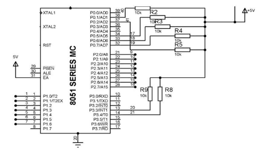
I2C is mostly used to connect microcontrollers and EEPROM. This is another name for the I2C master-slave protocol. Two signals make up I2C: a clock signal and a data signal. The clock signal, SCL, is under the Master's control. Data is transmitted using clock signal modification. The same clock drives every slave connected to the master. The interface with microcontrollers is depicted in the following figure:
The master IC can be connected to a variety of slave devices. Each slave has their own address, and the master device likewise has one. An LCD, a keyboard, a clock, a thermometer, or a memory interface could be the slave device. Here, the EEPROM will serve as the slave device and the I2C controller will serve as the master. For read or write operations, a set of control signals is sent. Address bits and data bits are included in these control signals. These control signals are accompanied by suitable clock signals.
EEPROM FAQ
What is the EEPROM?
Single bytes of data can be erased and reprogrammed using a non-volatile ROM called an EEPROM. As a result, EEPROM chips are additionally known as byte erasable chips. EEPROM is commonly used by computers and other electrical devices to store small amounts of data.
What is the speed difference between a parallel EEPROM (PEEPROM) and a serial device?
The 90 ns tAA speed of a PEEPROM is equivalent to about 11 MHz of serial clock speed. As a result, the PEEPROM's communication speed and capacity for simultaneous access to 8 or 16 bits enable high data transmission rates.
EEPROM vs EPROM
Both EPROM and EEPROM are erasable and reprogrammable, but the key distinction between the two is that EEPROM may be wiped using electric impulses whereas EPROM is erased using ultraviolet radiation.
Why use EEPROM over flash?
The lifespan capacity of an EEPROM is one million erase/rewrite cycles. Depending on the type of Flash memory, Flash devices have a limited lifespan; most flash products can withstand 10,000–1,000,000 erase/write cycles before damage begins to jeopardize the integrity of the storage.
Do parallel EEPROMs used in industrial and military equipment differ from one another?
Error Correction Coding (ECC) and error detection and correction are characteristics exclusive to the military version, which are also available in the industrial version. Every byte has four internal parity bits, and the Hamming technique is used to automatically correct the first bit error in every byte.
Since all 12 bits are tested, a mistake won't be visible until the second bit failure within the same byte. Because of the extremely minimal likelihood that this will occur, military products are extremely dependable.
Author: Calvin is a professional author who focuses on writing original articles related to IC chips and technology.


